f you’re pursuing a career in process piping, your expertise in engineering design technology will be applied to the design and development of process piping systems. Process piping systems, typically designed using AutoCAD, are utilized within the chemical, food processing, oil, gas and related industries to store and transport liquid and gaseous matter. Often carrying substances that are high in temperature and potentially hazardous, process piping systems and their associated components must be durable, functional and strategically constructed.
While completing your training in process piping and engineering design technology, one of the skills you’ll build is the ability to draw and design pressure vessels and other process piping components using AutoCAD. When it comes to the drawing of pressure vessels, having some background knowledge on the process can be helpful for producing a quality finished product. Below, discover a brief introduction to drawing pressure vessels.
The Function of Pressure Vessels Explained for Students in Process Piping Training
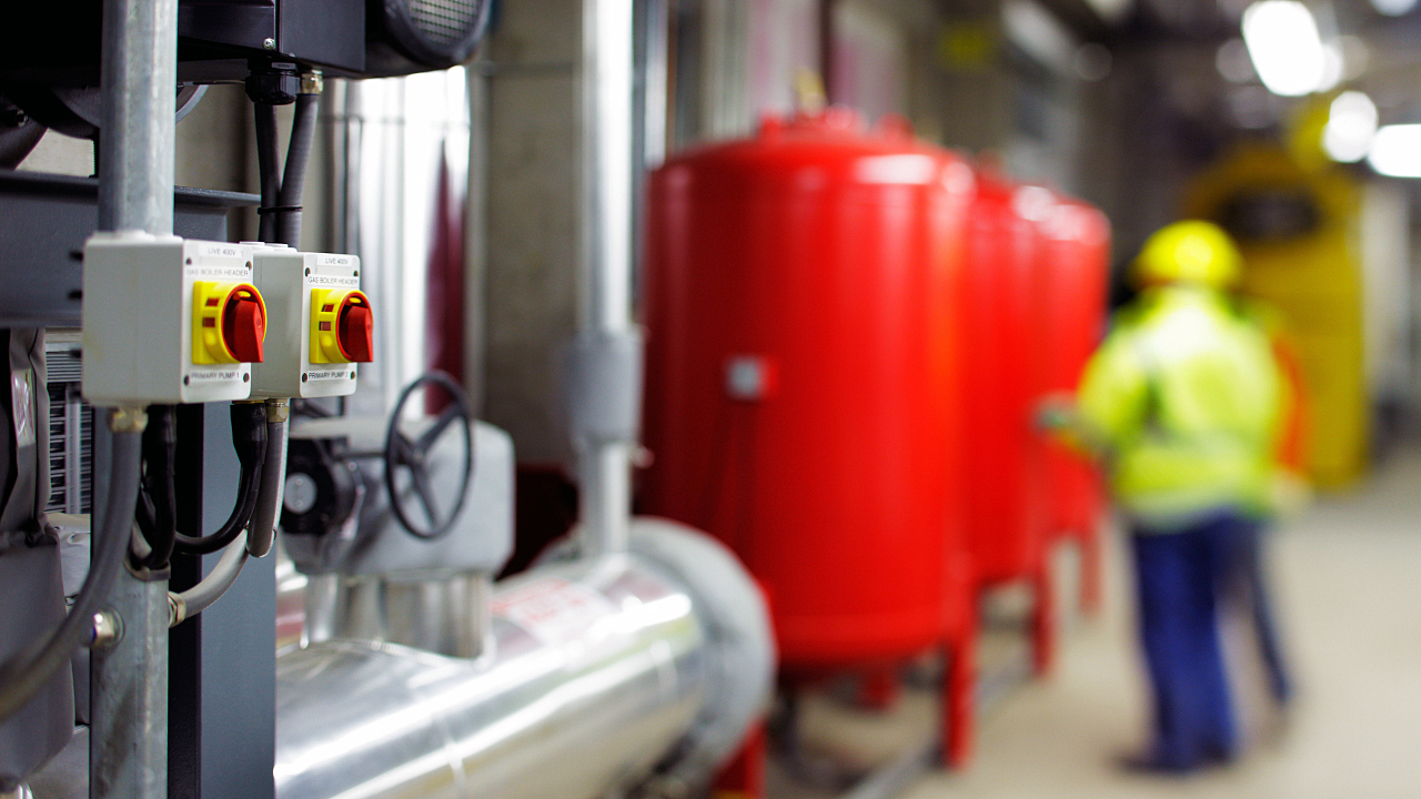
After completing your engineering design technology training, you may work on the design of pressure vessels for use in the petroleum, chemical processing, oil and gas and other industries. Pressure vessels are containers characterized by their leak-tight, closed quality. Typically spherical or cylindrical in design, these vessels hold gaseous or liquid matter at a specific pressure that differs from the outside environment. Pressure vessels can take on different forms, including boilers, reactors, heat exchangers, tanks and more. The most common materials used to assemble pressure vessels are stainless steel, aluminum, carbon steel and copper. If cylindrical, pressure vessels may take on either a vertical or horizontal shape. Both serve different purposes in terms of pressure distribution, and may require different forms of support for stability. During your career, keep these functional aspects in mind when designing pressure vessels.

After process piping training, you’ll design pressure vessels, which hold liquids or gases at a specific level of pressure
Components of Pressure Vessel Drawings
When utilizing AutoCAD software to draw a pressure vessel, you’ll want to make sure that you’ve included a few key components which are integral to the construction of any pressure vessel. The following parts are essential to any pressure vessel, including:
- Shell and head
- Process nozzles
- Drain nozzles
- Gaskets
- Flanges
- Lifting lug
- Skirt or support saddle
- Baseplate or ring
- Platforms, access ladders and handrails
After process piping training, you’ll want to ensure that each of these parts is accounted for within your drawing, and have been placed correctly in accordance with ASME Section VIII Boiler and Pressure Vessel Code standards. When designing a pressure vessel in AutoCAD, you’ll first determine the size and shape of the shell, which could be cylindrical or spherical, and if cylindrical, what kinds of supports it will need depending on whether it’s vertical or horizontal in orientation.
Tips for Designing and Drawing Pressure Vessels
When drawing pressure vessels in AutoCAD, there are a few tips you can keep in mind as you complete process piping programs online. One thing to note is that when approaching the process of pressure vessel drawing, it’s important to consider the intended use of the pressure vessel, as this will provide clarity when deciding the right type of container and supports to use. Consider where the container will be located, what kind of fluid or gaseous matter it will be holding, the operating pressure of the container and the temperature of its contents. Throughout your career, keeping all of these factors in mind will help you to determine the right materials and geometry for the pressure vessel you are designing, enhancing the accuracy and efficiency of the drawing process.


